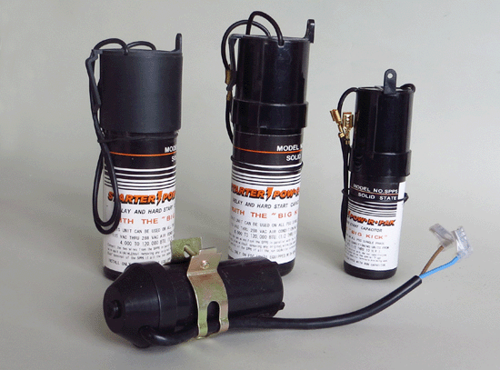
Fan Capacitor
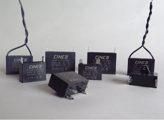
How do the fan capacitor work?
The most common motor used in a normal household electric fan is a single-phase induction motor. When first switched on such a motor needs to use a “starter” winding, in addition to its main winding, so that a rotating magnetic field is created to make the motor’s rotor start to turn.
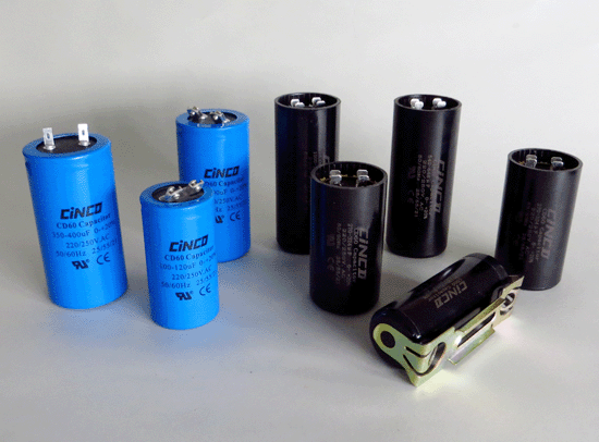
However a starter winding cannot do the job on its own, it needs a “Start-And-Run Capacitor” in series with the starter winding to create a rotating magnetic field. Without one of those capacitors the motor would never start to turn. 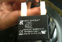
Most ceiling fans use a type of motor known as a “permanent split capacitor motor“. These motors have two coils, a “start” and a “run” winding. A capacitor is connected in series with the start winding to insert a phase shift, but once the motor is up to speed it becomes an auxiliary winding. In order to reverse the motor, the fan capacitor is applied to the “run” winding which then becomes the “start” winding. In some cases the windings may have taps to provide different speeds, in others the value of the start/run capacitor is lowered to provide lower speeds. Yet other designs will have additional capacitors wired in series with the motor as a whole to regulate speeds.
Feature:
1. small case, small dissipation factor, small in heterent temperature rise.
2. Fan Capacitor High insulation resistance.
3. Good self-healing characteristic.
4. Very good pressure resistance function.
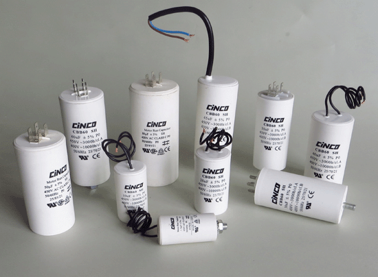
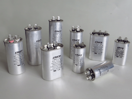
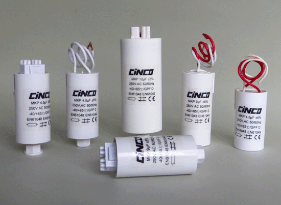
5. Fan capacitor Broadly applied to starting and running of AC single-phase motors at 50Hz(60Hz) frequency for AC fan, Ceiling Fan, centrifugal fan, cooling fan, axial fan, tube axial fan, centrifugal blower, fan guard, cross flow, industrial fans etc.
Specification:
| Rated capacitance | 1µF ~ 30µF |
| Tolerance | ± 5% |
| Rated voltage | 110VAC ~ 630VAC |
| Rated frequency | 50/60Hz |
| Maximum permissible voltage Vmax | 1.1 x VR (VR=Rated voltage) |
| Maximum permissible current Imax | 1.3 x IR (IR=Rated current) |
| AC test voltage terminal to terminal | 2 x VR, 2s (routine test) |
| 2 x VR, 60s (type test) | |
| Dissipation factor tan δ | ≤0.002 (50Hz) |
| Climate types | 40/85/21, 25/70/21 |
| Reference standards | IEC 60252-1 |
Ⅰ: Fan Capacitor Box type flexible wire
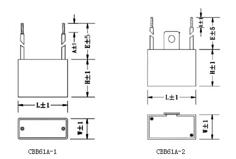
Ⅱ: Fan Capacitor Box type quick connect terminal
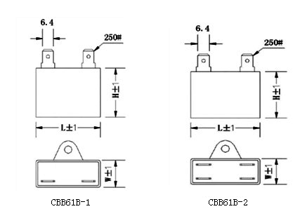
Dimensions:
| Capacitance |
400 VAC – 450VAC
|
250 VAC –300VAC
|
||||||||||
|
L
(mm) |
L
(inch) |
W
(mm) |
W
(inch) |
H
(mm) |
H
(inch) |
L
(mm) |
L
(inch) |
W
(mm) |
W
(inch) |
H
(mm) |
H
(inch) |
|
|
1μF
|
37
|
1.46″
|
15
|
0.59″
|
26
|
1.02″
|
37
|
1.46″
|
15
|
0.59″
|
26
|
1.02″
|
|
1.5μF
|
37
|
1.46″
|
15
|
0.59″
|
26
|
1.02″
|
37
|
1.46″
|
15
|
0.59″
|
26
|
1.02″
|
|
2μF
|
47
|
1.85″
|
18
|
0.71″
|
34
|
1.34″
|
37
|
1.46″
|
15
|
0.59″
|
26
|
1.02″
|
|
2.5μF
|
47
|
1.85″
|
18
|
0.71″
|
34
|
1.34″
|
37
|
1.46″
|
15
|
0.59″
|
26
|
1.02″
|
|
3μF
|
47
|
1.85″
|
18
|
0.71″
|
34
|
1.34″
|
37
|
1.46″
|
15
|
0.59″
|
26
|
1.02″
|
|
3.5μF
|
47
|
1.85″
|
18
|
0.71″
|
34
|
1.34″
|
37
|
1.46″
|
15
|
0.59″
|
26
|
1.02″
|
|
4μF
|
47
|
1.85″
|
18
|
0.71″
|
34
|
1.34″
|
37
|
1.46″
|
15
|
0.59″
|
26
|
1.02″
|
|
4.5μF
|
47
|
1.85″
|
18
|
0.71″
|
34
|
1.34″
|
37
|
1.46″
|
15
|
0.59″
|
26
|
1.02″
|
|
5μF
|
47
|
1.85″
|
18
|
0.71″
|
34
|
1.34″
|
47
|
1.85″
|
18
|
0.71″
|
34
|
1.34″
|
|
6μF
|
47
|
1.85″
|
18
|
0.71″
|
34
|
1.34″
|
47
|
1.85″
|
18
|
0.71″
|
34
|
1.34″
|
|
7μF
|
47
|
1.85″
|
18
|
0.71″
|
34
|
1.34″
|
47
|
1.85″
|
18
|
0.71″
|
34
|
1.34″
|
|
8μF
|
50
|
1.97″
|
23
|
0.91″
|
40
|
1.57″
|
47
|
1.85″
|
18
|
0.71″
|
34
|
1.34″
|
|
10μF
|
48
|
1.89″
|
28
|
1.10″
|
34
|
1.34″
|
50
|
1.97″
|
23
|
0.91″
|
40
|
1.57″
|
|
12μF
|
48
|
1.89″
|
28
|
1.10″
|
34
|
1.34″
|
50
|
1.97″
|
23
|
0.91″
|
40
|
1.57″
|
|
15μF
|
60
|
2.36″
|
28
|
1.10″
|
42
|
1.65″
|
50
|
1.97″
|
23
|
0.91″
|
40
|
1.57″
|
|
18μF
|
48
|
1.89″
|
28
|
1.10″
|
34
|
1.34″
|
48
|
1.89″
|
28
|
1.10″
|
34
|
1.34″
|
|
20μF
|
60
|
2.36″
|
38
|
1.50″
|
50
|
1.97″
|
48
|
1.89″
|
28
|
1.10″
|
34
|
1.34″
|
|
25μF
|
60
|
2.36″
|
38
|
1.50″
|
50
|
1.97″
|
60
|
2.36″
|
38
|
1.50″
|
50
|
1.97″
|
|
30μF
|
60
|
2.36″
|
38
|
1.50″
|
50
|
1.97″
|
60
|
2.36″
|
38
|
1.50″
|
50
|
1.97″
|
![]() if you could not find your item of above, you could contact me by email at sales@china-capacitores.com, Special specification are available on request.
if you could not find your item of above, you could contact me by email at sales@china-capacitores.com, Special specification are available on request.
Tags: Run Capacitor, Start Capacitor
